Search result
4 result(s) for " Cold-formed steel sections"
Defining Materials, Sections, and Thicknesses
/en/downloads-and-information/documents/online-manuals/rfem-6-tutorial/000160
Result Sections
/en/downloads-and-information/documents/online-manuals/rfem-6-tutorial/000209
Sections
/en/downloads-and-information/documents/online-manuals/rfem-6-tutorial/000162
Steel Columns
/en/downloads-and-information/documents/online-manuals/rfem-6-tutorial/000170


Length: 01:34:46 min
Length: 04:21:12 min
Length: 00:01:12 min
Length: 00:00:35 min
Length: 00:01:20 min
Length: 00:00:53 min
Length: 00:00:46 min
Length: 00:01:33 min
Length: 00:01:06 min
,_LC1__LI.jpg?mw=350&hash=a49d4e90c707e57dab1d5ce0c04d5d665393348d)
,_LC1__LI.jpg?mw=350&hash=a49d4e90c707e57dab1d5ce0c04d5d665393348d)
,_LC1__LI.jpg?mw=350&hash=a49d4e90c707e57dab1d5ce0c04d5d665393348d)


.png?mw=350&hash=b023d6c658e181cb7d69028c0f3994dedab96fc5)
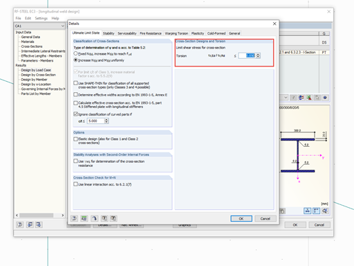
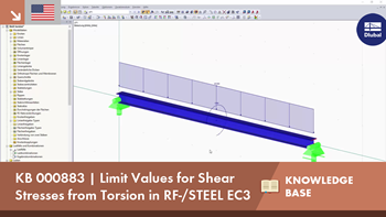
Very small torsional moments in the members to be designed often prevent certain design formats. In order to neglect them and still perform the designs, you can define a limit value in RF‑/STEEL EC3 from which torsional shear stresses are taken into account.
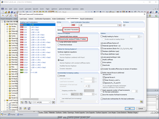
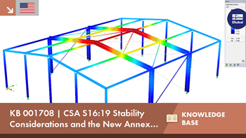
Structure stability is not a new phenomenon when referring to steel design. The Canadian steel design standard CSA S16 and the most recent 2019 release are no exception. Detailed stability requirements can be addressed with either the Simplified Stability Analysis Method in Clause 8.4.3 or, new to the 2019 standard, the Stability Effects in Elastic Analysis method provided in Annex O.
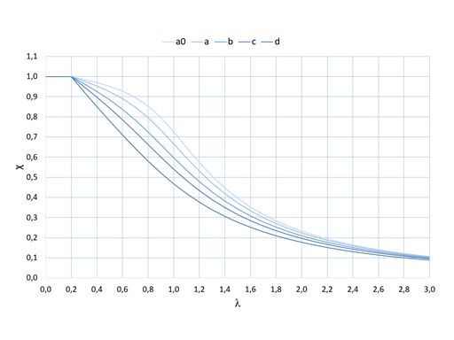
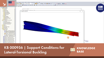
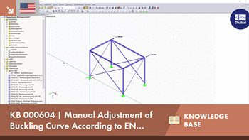
The RF‑/STEEL EC3 add-on module automatically transfers the buckling line to be used for the flexural buckling analysis for a cross-section from the cross-section properties. The assignment of the buckling line can be adjusted manually in the module input for general cross-sections in particular, as well as for special cases.
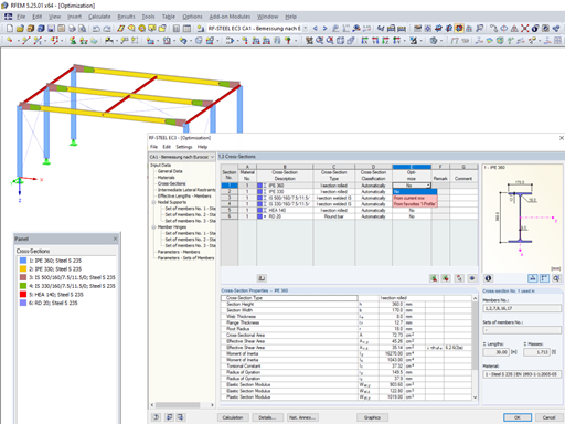
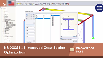
When optimizing cross-sections in the add-on modules, you can also select arbitrarily defined cross-section favorites lists - in addition to the cross-sections from the same cross-section series as the original cross-section.


In the ultimate configuration of the steel joint design, you have the option to modify the limit plastic strain for welds.

Using the "Base Plate" component, you can design base plate connections with cast-in anchors. In addition to plates and welds, the design analyzes the anchorage and the steel-concrete interaction.
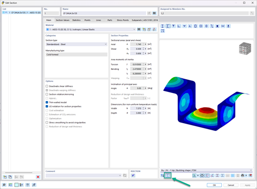
In the "Edit Section" dialog box, you can display the buckling shapes of the Finite Strip Method (FSM) as a 3D graphic.

- Design of five types of seismic force-resisting systems (SFRS) includes Special Moment Frame (SMF), Intermediate Moment Frame (IMF), Ordinary Moment Frame (OMF), Ordinary Concentrically Braced Frame (OCBF), and Special Concentrically Braced Frame (SCBF)
- Ductility check of the width-to thickness ratios for webs and flanges
- Calculation of the required strength and stiffness for stability bracing of beams
- Calculation of the maximum spacing for stability bracing of beams
- Calculation of the required strength at hinge locations for stability bracing of beams
- Calculation of the column required strength with the option to neglect all bending moments, shear, and torsion for overstrength limit state
- Design check of column and brace slenderness ratios
I am designing a set of members using the equivalent member method in RF‑/STEEL EC3, but the calculation fails. The system is unstable, delivering the message "Non-designable - ER055) Zero value of the critical moment on the segment".
What could be the reason?
Why are the equivalent member design checks grayed out in the Stability tab when activating the plastic design using the partial internal force method (RF‑/STEEL Plasticity)?
How can I create a drilled beam in RFEM?
In connection with a calculation according to the large deformation analysis, I get significantly smaller deformations than for a calculation according to the linear static or second-order analysis. How is this possible?
How does the activation of the precamber imperfection work?
Are the models and presentations from Info Day 2020 freely available, and can you send them to me?


